Element evaluation is performed on a sample of randomly selected parts from a production lot, (if die, they are assembled into packages). These parts are then subjected to a series of tests selected to verify the reliability of the parts (Electrical, screening, environmental, endurance and mechanical tests) and the production lot from which they originated.
The Element Evaluation is performed to show that the parts performance, materials and manufacturing processes are able to meet their specified electrical, mechanical and physical performance characteristics for which they were designed-and as a result, their suitability for use in the application in which they are intended to be used.
It is essential to perform the element evaluation prior to use in production and to verify all materials prior to their use in production devices to minimise the risks of a lot failure (see table C-I).
The Element evaluation flow may vary or be modified by the manufacturer based on:
- Element quality and reliability history.
- Device quality and reliability history.
- Best commercial practice/Supplier history.
- Supplier/manufacturer relationship.
- Possible impact of element evaluation failure after assembly
The purpose of the Element Evaluation is to assess the performance, quality and reliability of each of the parts to be used in the assembly of a hybrid to minimise latent failure mechanisms, catastrophic failures and rework.
Test samples are usually assembled following industry standard processes that are similar to the assembly methods and conditions to be used in the Hybrid production assembly. This information originates from the users/customers/manufacturers making the hybrids.
Element Evaluation is performed following an approved set of standards and processes within a controlled and approved specification MIL-PRF-38534. There are five levels of test/reliability within this document, and the level selected depends on the Programme P.A. requirement, the level of assurance, schedule and cost for the intended application.
Element Evaluation by Family
| wdt_ID | Element | Paragraph | Table C-I MIL-PRF-38534J |
|---|---|---|---|
| 1 | Microcircuit and semiconductor dice | C.3.3 | Table C-II |
| 2 | Passive elements | C.3.4 | Table C-III |
| 3 | Surface acoustic wave | C.3.5 | Table C-IV |
| 4 | Alternate evaluation | C.3.6 | N/A |
| 5 | Substrate evaluation | C.3.7 | Table C-V |
| 6 | Package evaluation | C.3.8 | Table C-VI |
| 7 | Integral substrate/package evaluation | C.3.9 | Table C-VII |
| 8 | Polymeric material evaluation | C.3.10 | Method 5011 from MIL-STD-883 |
Non Destructive Test Steps performed by 100%
MIL-PRF-38534 Class H or K – Required activities 100% (Subgs 1 & 2)
- Subgroup 1: Element Electrical (to die level)
- Option 1: guaranteed by MFR (included in received documentation)
- Option 2: waiver to remove this verification accepted by customer
- Subgroup 2: Element Visual or Visual Inspection
- It could be guaranteed by MFR included in received documentation but in any case, this inspection is performed by Alter Technology during Incoming Inspection only on top surface (not touching the DUT)
| EEE Part | wdt_ID | Subgroup | Class | Test | MIL-STD-883 | Quantity (accept number) | Reference paragraph |
|---|---|---|---|---|---|---|---|
| IC & Semiconductor | 1 | 1 | K / H | Element electrical | 100 percent | C.3.3.1 | |
| IC & Semiconductor | 2 | 2 | K / H | Element visual | 2010 1* /2069 1* /2070 1* /2072 1* /2073 * MIL-STD-750 methods. |
100 percent | C.3.3.2 |
| Passive | 3 | 1 | K / H | Element, Electrical | 100 percent | C.3.4.1 | |
| Passive | 4 | 2 | K / H | Visual inspection | 2032 | 100 percent | C.3.4.2 |
Destructive Test Steps performed by sampling
MIL-PRF-38534J Class H – (Subgroups 3, 4, 5 & 6)
- ATN test plan
- Assembly process
- Subgroup 3: Visual inspection on assembled dice
- Subgroup 4: Final electrical or Element Electrical
- Electrical parameters are defined by ATN in RFQ step
- Subgroup 5: Wire bond evaluation (bond pull test)
- ATN report
MIL-PRF-38534J Class K IC & Semiconductor – (Subgroups 3, 4, 5 & 6)
- ATN test plan
- Assembly process
- Subgroup 3: Visual inspection on assembled dice
- Subgroup 4a: Temperature Cycling
- Subgroup 4b: Mechanical Shock or Constant acceleration
- Subgroup 4c: Interim Electrical
- Electrical parameters are defined by ATN in RFQ step
- Subgroup 4d: Burn-In
- Subgroup 4e: Post- Burn-In Electrical
- Electrical parameters are defined by ATN in RFQ step
- Subgroup 4f: Steady-State Life
- Subgroup 4g: Final electrical or Element Electrical
- Electrical parameters are defined by ATN in RFQ step
- Subgroup 5: Wire Bond evaluation (bond pull test)
- Subgroup 6: SEM
- ATN report
| wdt_ID | EEE part | Subgroup | Class | Test | MIL-STD-883 | Quantity (accept number) | Reference paragraph MIL-PRF-38534J |
|---|---|---|---|---|---|---|---|
| 1 | IC & Semiconductor | 3 | K / H | Internal Visual | 2010 1* /2069 1* /2070 1* /2072 1* /2073 * MIL-STD-750 methods. |
10 (0) | C.3.3.3 C.3.3.4.2 |
| 2 | IC & Semiconductor | 4 | K | Temperature cycling | 1010 Condition C | 2/ 10 (0) | C.3.3.3 |
| 3 | IC & Semiconductor | 4 | K | Mechanical shock or Constant | 2002 Condition: B, Y1 direction 2001 Condition: 3000 g´s Y1 direction |
2/ 10 (0) | |
| 4 | IC & Semiconductor | 4 | K | Interim electrical | 2/ 10 (0) | C.3.3.4.3 | |
| 5 | IC & Semiconductor | 4 | K | Burn-in | 1015 Condition: 240 hours minimun at +125ºC |
2/ 10 (0) | |
| 6 | IC & Semiconductor | 4 | K | Post burn-in electrical | 2/ 10 (0) | C.3.3.4.3 | |
| 7 | IC & Semiconductor | 4 | K | Steady-state life | 1005 | 2/ 10 (0) | |
| 8 | I & C Semiconductor | 4 | K / H | Final electrical | 2/ 10 (0) | C.3.3.4.3 | |
| 9 | IC & Semiconductor | 5 | K / H | Wired bond evaluation | 2011 | 10 (0) wires or 20 (1) wires | C.3.3.3 C.3.3.5 |
| 10 | IC & semiconductor | 6 | K | SEM | 2018 1* /2077 * MIL-STD-750 methods. |
See method 2018 of MIL-STD-883 or method 2077 of MIL-STD-750 | C.3.3.6 |
Element Evaluation Procedure
Specific test plan is issued by Alter Technology to establish the requirements and conditions for the performance of Element Evaluation Test in order to reach the confidence level required by the customer, in accordance with the described test sequence.
- Special custom substrate designed and manufactured by Alter Technology:
- Gold plated pads
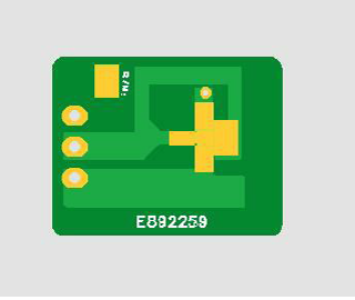
- Gold plated pads
- Substrate cleaning process:
- Plasma 95% Argon / 5% Oxygen
- Die assembly (manual dispense):
- ABLESTIK ABLEBOND JM7000
- ABLESTIK ABLEBOND 967-1
- ABLESTIK 84-1LMISR4
- EPO-TEK H20E
- Die attach cure (conditions depending of the material)
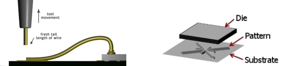
- Wire bonding:
- 25µm diameter gold or aluminium wire
- Thermosonic ball or wedge process
MIL-PRF-38534 Class H or K Subgroup 3: Visual inspection on assembled dice
- Each sample will be visually inspected to ensure conformance with the applicable requirements of MIL-PRF-38534 Class K or H, MIL-STD-883 method 2010.

MIL-PRF-38534 Class H or K Subgroup 4: Final electrical or Element Electrical
- Final electrical tests, the minimum requirements for passive, microcircuits and semiconductor dice will include DC static parameters (detailed at RFQ step) at room temperature.
| wdt_ID | Nº | Test | Conditions | Limits MIIN | Limits MAX | Unit |
|---|---|---|---|---|---|---|
| 1 | 1 | Vp | Vds=2V; lds=1.60mA | -1.5 | -0.5 | V |
| 2 | 2 | BVgd | lg=1.60mA; source open | -- | -12 | V |
| 3 | 3 | ldss | Vds=2V; Vgs=0V | 320 | 714 | mA |

MIL-PRF-38534 Class K Subgroup 4: Temperature Cycling
- Temperature Cycling test is performed iaw MIL-STD-883 T.M. 1010 Cond. C
- This test is conducted to determine the resistance of a part to extremes of high and low temperatures, and to the effect of alternate exposures to these extremes.

MIL-PRF-38534 Class K Subgroup 4: Mechanical Shock
- Mechanical Shock test is performed iaw MIL-STD-883 T.M. 2002 Cond. B Y1
- The shock test is intended to determine the suitability of the devices for use in electronic equipment which may be subjected to moderately severe shocks as a result of suddenly applied forces or abrupt changes in motion produced by rough handling, transportation, or field operation. Shocks of this type may disturb operating characteristics or cause damage similar to that resulting from excessive vibration, particularly if the shock pulses are repetitive.

MIL-PRF-38534 Class K Subgroup 4: Constant Acceleration
- Constant Acceleration test is performed iaw MIL-STD-883 T.M. 2001 3Kg Y1
- This test is used to determine the effects of constant acceleration on microelectronic devices. It is an accelerated test designed to indicate types of structural and mechanical weaknesses not necessarily detected in shock and vibration tests. It may be used as a high stress test to determine the mechanical limits of the package, internal metallization and lead system, die or substrate attachment, and other elements of the microelectronic device.

MIL-PRF-38534 Class K Subgroup 4: Burn-In
- Burn-In test is performed iaw MIL-STD-883 T.M. 1015 240h at +125°C
- The burn-in test is performed for the purpose of screening or eliminating marginal devices, those with inherent defects or defects resulting from manufacturing aberrations which cause time and stress dependent failures. In the absence of burn-in, these defective devices would be expected to result in infant mortality or early lifetime failures under use conditions. Therefore, it is the intent of this screen to stress microcircuits at or above maximum rated operating conditions or to apply equivalent screening conditions, which will reveal time and stress dependent failure modes with equal or greater sensitivity.

MIL-PRF-38534 Class K Subgroup 3 – Passives: Voltage conditioning or aging
- Voltage conditioning or aging shall be performed in accordance with the appropriate passive device specification. When there is no applicable device specification, or the requirements of the device specifications are not appropriate, the manufacturer shall document the procedure being used. Below are some examples of performance specifications used for example passive element conditioning requirements:
- Resistors: MIL-PRF-914
- Capacitors: MIL-PRF-123
- Coils or Transformers: MIL-PRF-27
MIL-PRF-38534 Class K Subgroup 4: Steady-State Life
- Steady-State Life test is performed iaw MIL-STD-883 T.M. 1005
- The steady-state life test is performed for the purpose of demonstrating the quality or reliability of devices subjected to the specified conditions over an extended time period. Life tests conducted within rated operating conditions should be conducted for a sufficiently long test period to assure that results are not characteristic of early failures or “infant mortality,” and periodic observations of results should be made prior to the end of the life test to provide an indication of any significant variation of failure rate with time.
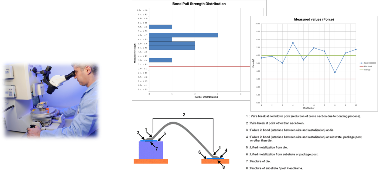
MIL-PRF-38534 Class H or K Subgroup 5: Wire bond evaluation (bond pull test)
- Bond pull test is performed iaw MIL-STD-883 T.M. 2011 Cond. D
- Wire bond strength testing applies to elements which are wire bonded during the device assembly operation.
MIL-PRF-38534 Class K Subgroup 6: SEM
- SEM inspection is performed iaw MIL-STD-883 T.M. 2018 & 2077
- This method provides a means of judging the quality and acceptability of device interconnect metallization on non-planar oxide integrated circuit wafers or dice. This method should not be used as a test method for workmanship and other type defects best identified using method 2010.

Alter Technology report is issued to detail all the technical concepts assessed during the performed element evaluation test flow, including the following information:
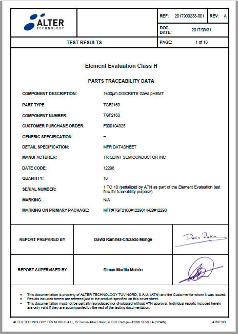
- Traceability information
- Summary
- Test reports
- Test method
- Conditions / parameters / limits
- Remarks
- Conclusion
- Records
- List of equipments