Low Temperature Radiation Test of High Voltage Optocouplers for Space Applications
Introduction
Previous studies in radiation induced degradation in optocouplers at room temperature indicated that the most affected parameters were CTR and dark current (1,2). This fact is also applicable to high voltage (HV) optocoupler where the working voltage could go up to 10KV.
In space applications, optocouplers may need to work at very low temperatures. Under this low temperature operating conditions, the device degradation subjected to radiation exposure may show different behaviour compared to a standard radiation test under room temperature. The purpose of this paper is to analyse the effects of proton displacement damages up to 8•1011p/cm2 and total ionisation dose up to 100Krad (Si)) at room and low temperature (i.e. 25ºC and -40ºC) on custom assemblies of High Voltage (HV) Optocouplers. The HV opto-coupler assembly, radiation setups for low temperature Gamma and Displacement Damage radiation tests are described in detailed.
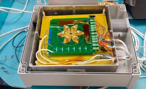
Radiation testing board with six HV optocouplers
The radiation testing board consists of six optocouplers connected in parallel with a protection resistor of 1MΩ. During either proton radiation or gamma radiation exposure, the monitored parameter at low temperature was the Current Transfer Rate when LEDs IF= 1 mA and optodiode VRWM = 5kV.
Low Temperature Radiation Setup
Both gamma and proton radiation had to be performed with the possibility of keeping an optocoupler at a stable temperature of -40ºC at the radiation facility. Several cooling options were considered. Finally, it was decided to use a small chamber with a window being cooled with liquid nitrogen in a close loop configuration to allow precise PID temperature control of the samples. A small (approx. 100 liters) liquid nitrogen vessel was required near the radiation area and it was filled periodically to keep the temperature stable. Figure 2a shows the gamma radiation set up whereas figure 2b shows the proton radiation set-up at proton radiation facility.
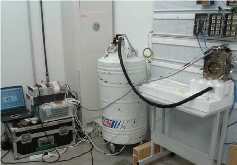
Gamma radiation set-up
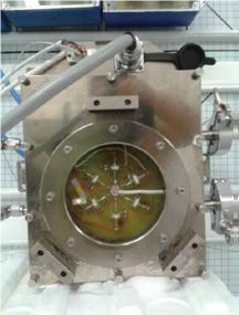
Gamma radiation set-up
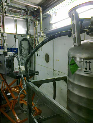
Proton radiation set-up
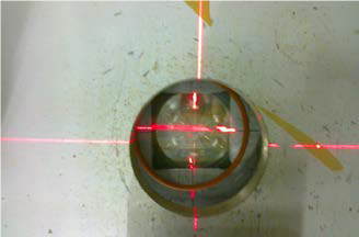
Proton radiation set-up
Radiation Campaign
Proton radiation campaign was performed at the Cyclotron Resource Centre at the Université Catholique de Louvin (UCL). The Cyclone is a multiparticle, variable energy, cyclotron capable of accelerating protons up to 65 MeV. Table I show proton radiation conditions applied to the HV optocouplers.
Gamma radiation campaign was performed at the RADLAB (Gamma Radiation Laboratory) at the Centro Nacional de Aceleradores-CNA (University of Seville, CSIC & Junta de Andalucía). The RADLAB is based on a 60Co gamma radiation source, the dose rate uniformity in the radiation field was better than 95% and the expanded uncertainty associated with the measurement is +/- 4.2%. Table II show gamma radiation conditions applied to the HV optocouplers.
The intermediate measurements performed after each proton and gamma radiation step are described in table III. The dark current at VRWM=1kV and VRWM=5kV, the forward voltage at IF from 0 to 10 mA and the CTR (Current Transfer Rate) at VRWM=1kV and VRWM=5kV and IF= 0.1 mA and 1 mA, were measured at each intermediate step.
Results
- Gamma Radiation Test Results
Results of the gamma radiation test have shown that there was no optocouplers degradation. For example the dark current at low temperature was obviously lower than at room temperature, but it showed no degradation during the low temperature radiation test. It clearly recovered the same value when measured during annealing stage at room temperature.
The following picture shows the CTR evolution after each gamma radiation step. It did show no degradation. All the other results obtained were similar in the sense that only variations with respect to different temperature was observed, but no gamma radiation related degradation has been noticed.
- Proton Radiation Test Results
However, the proton radiation tests have given rather more interesting results. In this case, there is real optocouplers degradation. The device degradation has been found to be different at low temperature (-40ºC) and at room temperature.
The CTR percentage reduction which was calculated from the above data at the indicated conditions. Note that for a LED forward current of 1mA results at 25ºC and -40ºC are equivalent, but for lower LED forward current of 0.1mA results at 25ºC and -40ºC are completely different as CTR reduction at -40ºC is almost 5 times higher than the CTR reduction at 25ºC.v
The arrows at each step indicate the moment when the proton radiation started and when it was removed. It was detected some annealing effect after each radiation step. CTR degradation during the test had a similar rate in all steps. However, this rate was different for some minutes during the 3rd step. It is believed that the cause of this change was that the flux was unintentionally increased up to 2×10⁸ p/s/cm2 during those minutes. Although, the final step fluence was 6×10¹¹ p/s/cm2 as specified in the test plan procedure.
The graph below shows the dark current evolution measured at each intermediate step. Note that the first and the last measurements were taken at 25ºC while the other measurements were taken at -40ºC. These results are not uncommon as the dark current strongly depends on the temperature.
- LED Technologies & Properties - 2nd February 2016
- Fast optical source for quantum key distribution based on semiconductor optical amplifiers - 1st February 2016
- Low Temperature Radiation Test of High Voltage Optocouplers for Space Applications - 1st February 2016


