ALTER TL-FP3421 provides an efficient way to control and monitor the current status of a 19” Galileo COTS-based system with three LEDs, and one more LED indicates if the system is power supplied or not.
The LEDs status represents up to 16 main different status according to customized truth status table. More number of states could be available by using different LEDs ON at the same time.
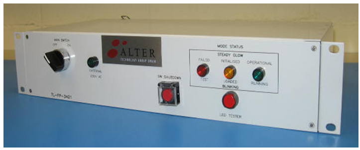
Front Panel unit monitors the equipment running status and, optionally, it turns on/off the system by managing the power electrical.
It also monitors the presence of power in the system and is provided with a tester button for checking that the three status LEDs are operative.
Front Panel Overview
In the front panel there’s also a single SW shutdown button, and the main power switch, for some model versions (v1 and v2)
In rear side there are 4 AC connectors, one earthling point and one DB25, DB9 or USB connector for data connections.
FEATURES:
- 220V 50Hz power supplied.
- Main electrical switch common for two independent input electrical circuits.
- 220v ON/OFF green indicator diode fully replaceable by frontal access.
- LED Tester button.
- 1 DB25 rear connector for 3.3v input signalling based on GPIO. Also available USB rear connector model with internal signal conversion.
- 4 polarized AC power supply connectors
- 3 LED status fully replaceable by frontal access (blinking and steady-glow functionality).
- 1 functional control shutdown press button (optional).
- CE marked.
- 2 years warranty.
Front Panel Functional Description
The LED test button verifies the correct operational status of each LED.
The LEDS are based on an internal PAL memory, programmed according to a truth table to show the following equipment status:
| wdt_ID | Light | LABEL | Status | DESCRIPTION |
|---|---|---|---|---|
| 1 | Power AC presence | External 230v AC | - | Indicates that there is 230 Vac of protected power supplying the system |
| 2 | Status RED | Failed | Steady glow | The system is in Failed state |
| 3 | Status ORANGE | Initialised | Blinking | The system is in Initialised state |
| 4 | Status GREEN | Operational | Steady glow | The system is in Operational state |
| 5 | Status RED | Test | Blinking | The system is in Test state |
| 6 | Status ORANGE | Loaded | Steady glow | The system is in Loaded state |
| 7 | Status GREEN | Running | Blinking | The system is in Running state |
| Light | LABEL | Status | DESCRIPTION |
Front Panel rear connector distribution
The Front Panel manages equipment power electrical control, by using a double internal circuit short-break which controls 230Vac power supply before and after UPS unit.
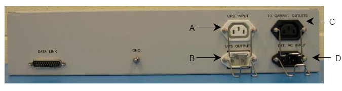
- AC module controls 220v power supply for the cabinet COTS and isolates completely the whole charge when main
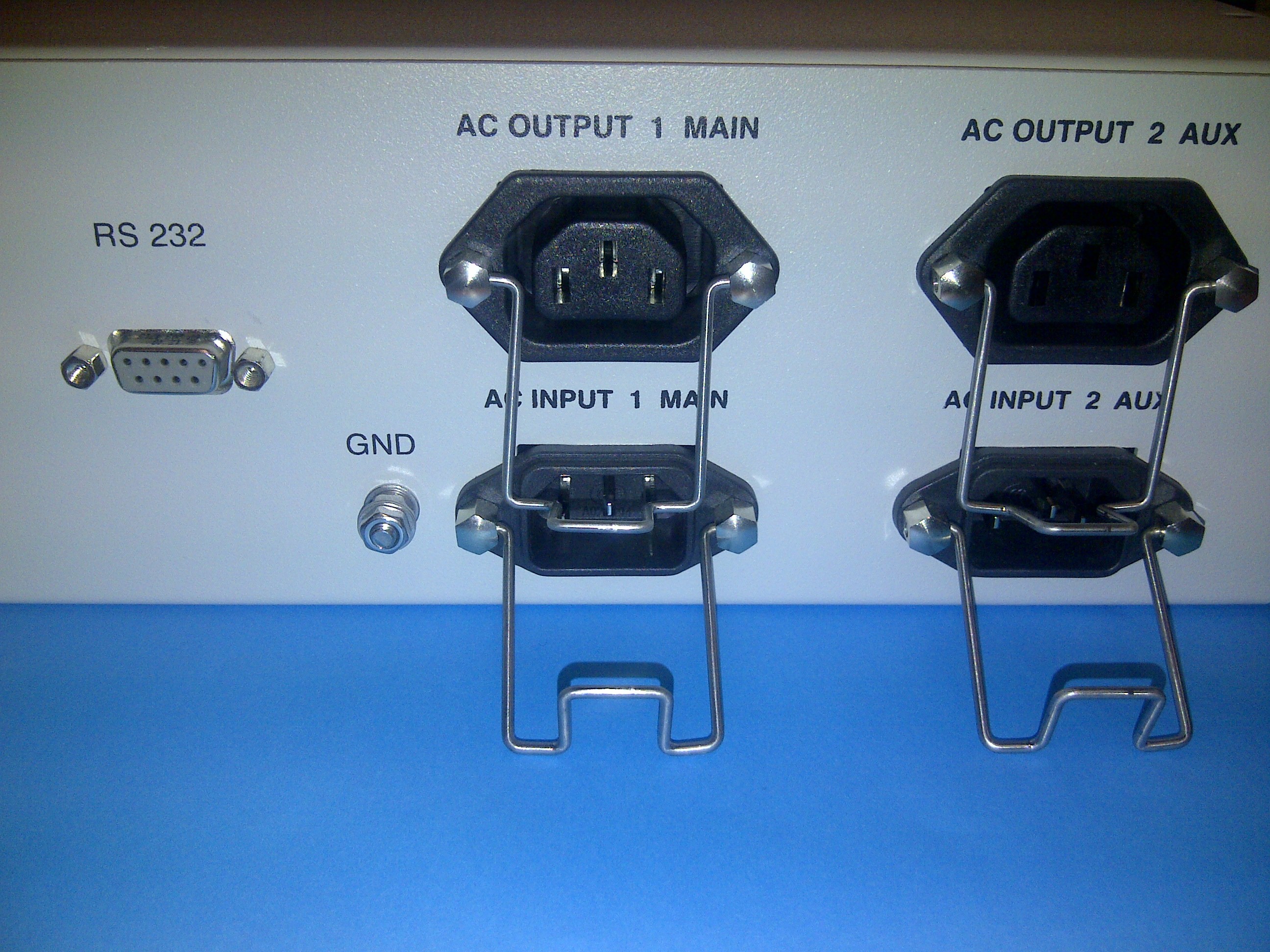
Figure: Front Panel v5 DB9 modification and rear connectors’ distribution overview
switch is off for both electrical inputs. LED signal for the 220v ON/OFF evidence.
- DC module is responsible of power supplying logic circuits and generates the appropriate LED status lighting according to input signalling.
Polarized AC connectors prevent the short-circuit of the charge providing at the same time fast and easy replacement of a Front Panel unit.
An additional push button to invocate the shutdown of SW system’s procedures, previous to electrical shutdown, is available.