Lead integrity test is performed to determine the integrity of the device leads (terminals), welds and seals. During the execution of this test, the DUT is subjected to various stresses including tension, bending fatigue and torque. The stresses to be applied depend on the DUT characteristics and on the corresponding test method.
Once the required activities have been completed, the DUT is submitted to external visual inspection and is examined under magnification to determine any evidence of breakage, loosening or motion between the terminal and the device body that would compromise the long term reliability of the parts.
As an example, MIL-STD-883, TM 2004.7 specifies the following options for lead (terminal) integrity testing:
- Test condition A provides for straight tensile loading on leaded parts.
- Test condition A1 provides testing the solder or braze material lead attach on packages with brazed leads, that is, leadless packages with solderable pads.
- Test condition B1 provides for application of bending stresses to determine integrity of leads and seals.
- Test condition B2 employs multiple application of bending stresses primarily to determine the resistance of the leads to metal fatigue under repeated bending.
- Test condition C provides for application of torque stresses to device leads to determine integrity of leads and seals.
- Test condition D provides for application of peel and tensile stresses to determine integrity of terminal adhesion and plating of leadless packages.
- Test condition E provides for application of bending sresses to check the lead plating for flexible and semi-flexible leads.
Since parts are submitted to different forces during the handling, soldering and testing processes, this test is intended to demonstrate the effect of stresses applied on the seal as well as on the leads.
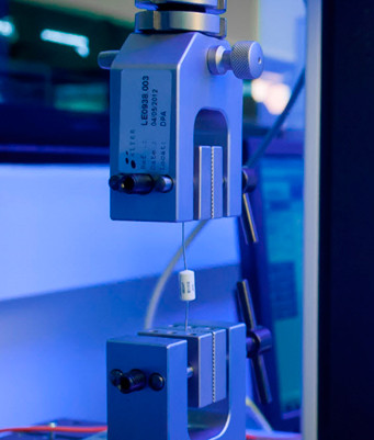
An advanced force multitester is used for measuring the tensile strength of leads. The system software allows the operator to control the equipment as well as to collect and display the obtained data. In this test it is very important to ensure that the leads will not break or detach during the lead-forming process previous to assembling the parts on a PCB.
The lead fatigue equipment system includes three controls (bend angle, bend speed and number of cycles) as well as automatic stop sensors.
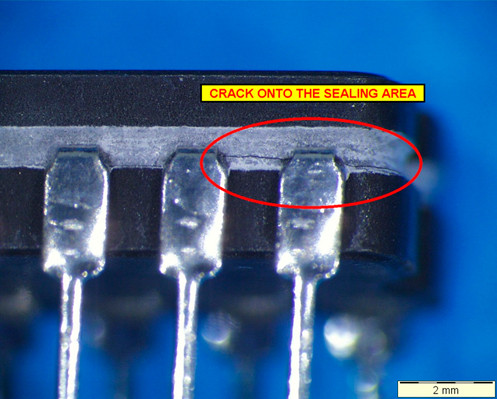
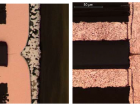
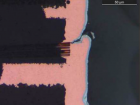
FIGURE: Crack onto the sealing area after a lead integrity test.

He is also specialized in the internal inspection of microcircuits and hybrids technologies.
- Resistance to Solvent or Marking Permanence Test | EEE Parts - 21st January 2016
- Lead Integrity Test Electronic Components | EEE Parts - 9th December 2015
- Bond Pull Test Electronic Component | EEE Parts - 4th December 2015