Talk summary:
- Some background information about BMTI will be introduced. 1. Using built-in self-test (BIST) structures for SEE test BIST structures, scan chains and memory-BIST, are used in SEE hardness assurance of BMTI’s IC products. The basic principle, consideration and skills will be given. Some implications for SEE assurance will be discussed.
- SEE failure analysis and SEL evaluation with laser Laser is applied to analyze the failure mechanism and position of SEE errors, and to evaluate the SEL hardness of ICs. Some examples will be given.
- Test method for distinguishing SEU and SET, and SET analysis BMTI proposed a method to distinguish SEUs and SETs, and analyze SETs in details. With this method we can obtain more implications for design and test without additional beam time and cost. The principle of this method and some application examples will be shown.
- BMTI’s featured SEE test modules Two modules for SEE testing to improve the test capability and efficiency will be introduced.
Radiation Test experience at BMTI
Introduction
Who is BMTI?
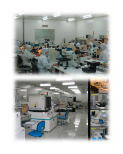
BMTI is a China leading organization in radiationhardened microelectronics research. Also, is the largest radiationhardened IC provider in China. The main achievements include:
- Several high-reliability RH IC design platforms
- A complete RH IC product family
- Advanced packaging, testing, and 4-inch fab line
They have three Radiation – Hardening Platforms where they work with different thresholds of mesurement that come drift in three Platform in ascent from 2002 to 2020:
- Mature Platform ——– 10 kgate to 3,000 kgate
- Developing Platform — 10,000 kgate
- Planning Platform —— 100,000 kgate
BMTI has been developing a large Space IC Product Family and a huge packaging, testing and fab lines.
Using built-in self-test (BIST) structures for SEE test
Problem with SEE testing of complex ICs
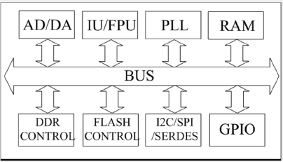 A typical complex IC:
- Many modules
- many function modes
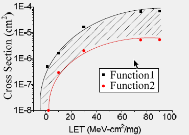 Different cross sections for different function
SEE testing based on built-in self-test (BIST)
Built-in self-test (BIST) is a popular and even mandatory design-for-test (DFT) method in nowaday IC designs.
Two of BIST features, Scan chains and Memory BIST (MBIST) can be used for evaluating SEE performance of ICs.
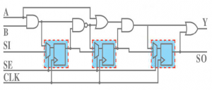
Scan Chain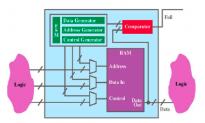
MBIST
Almost 100% of sensitive modules in ICs can be
covered by BIST test
Comparison between Function and BIST SEE test
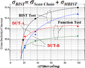 σBIST is always greater than σFunction
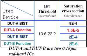
SEE test with BIST is a worst-case test
BIST test result can be a conservative estimation of any function test results
Effective fluence in SEE test with MBIST
Memory BIST
The sequence and timing of MBIST operation is determined by embedded arithmetic, but can’t be adjusted.
Not all SEUs can be detected due to self refresh by write operation.
Effective fluence should be calculated according to the MBIST arithmetic. By considering effective fluence, SEE test with MBIST can accurately evaluate the SEU performance of embedded memories.
SEE failure analysis with laser
- Using laser for SEE test
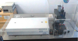
Pulsed laser is a good tool to estimate SEE performance of ICs. In BMTI, we mainly take advantage of laser for:
Positioning of SEE errors/failures:
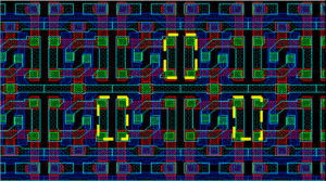 Positioning of SEU Sensitive Node in an SEU-hardened SRAM.
⇒ According to the laser result, TCAD simulation gives the reasons for the sensitivity:
- Charge sharing between NMOS
- Charge sharing between NMOS and PMOS, and the bipolar amplification of the PMOS.
⇒ According to laser and simulation analysis, the SRAM was redesigned by modifying its bit cell:
- Spacing between sensitive nodes increases by 2.7x in an area-efficient manner:
- Negligible cost of power and performance.
Failure Analyzing of SEE-induced Burnout:
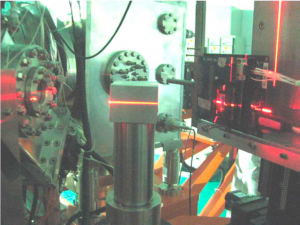
⇒ Laser test shows that:
- Direct strike on the ESD transistor doesn’t induce burn-out.
- Burn-out was found after the strike on the capacitor in the ESD structure.
⇒ MechanismAnalysis:
- The capacitor in the ESD structure can be broken down by irradiation, leading to large current and then burnout.
Ion test is difficult to position a failure source when the failure mode and the source node are different, while laser test can do this well.
Test method for distinguishing SEU and SET, and SET analysis
As process technology advances, the ratio of typical SET pulse width (PW) and typical circuit period increases, making SETs easier to be captured by sequential cells.
The ratio of typical SET PW and typical cell delay increases, making SETs easier to propagate on logic paths.
Time domain test and analysis
- Record errors every Δt during irradiation
- Δt≤0.1s to make sure only one event happens during Δt
- Plot error accumulation with time for each type of ions
- SEU and SET can be distinguished by observing time-domain plot
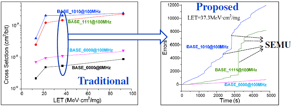
- Plotting errors in time domain provides insight to the detailed process of error accumulation
- Discrete jumps in the time-domain curves indicate single-event multiple-cell upsets (SEMU)
- Single events on global signals such as clock and reset can cause SEMUs (as large as several thousand upsets)
Download or read the full report here
- Quantum Key Distribution - 7th November 2022
- Conducted Immunity - 20th May 2019
- Electrical transients Test - 2nd May 2019


