Analysis of Inspection and DPA Test Requirements applied to Flip Chip Technologies.
Background and motivations.
Flip chip assembly techniques bring a wide range of benefits:
- A reduced parasitic interconnection between the semiconductor die and package.
- Provides a high final assembly integrity density.
- Minimize the interconnection length, providing better electrical performances, especially for high-speed signals.
- Reduce device size and weight,…, etc.
Study approach / Tasks.
Task 1 – Investigate Requirements.
Task 2 – Research Solutions.
Task 3 – Analysis of Solutions.
Task 4 – Demonstrations.
Flip Chip Technologies, Reliability and Failure Modes
| wdt_ID | Process | Failure Mode | Failure Mechanism |
|---|---|---|---|
| 1 | Solder ball attach | Missing bumps | Poor process set up |
| 2 | Physical Damage | ||
| 3 | Fractured bumps | Poor process set up | |
| 4 | Poor wetting | Poor process set up | |
| 5 | Bump Height | Poor process set up | |
| 6 | Bump Alignment | Mask design / Poor process set up | |
| 7 | Alignment / placement of die by flip chip border | Cracked die | Uneven bump height |
| 8 | Contanimation | ||
| 9 | Variation in material strength | ||
| 10 | Stressed Die | Uneven bump height | |
| Process | Failure Mode | Failure Mechanism |
Flip Chip Technologies, Requirements investigations
MIL
- MIL-STD-883 J , MIL-STD-1580B
- MIL-PRF-38535 K, EPS on Flip-Chip underfill test requirements
IPC
- IPC-7094 on Design and assembly process implementation for Flip-chip, MIL-STD-1580 B,
- IPC-TM-650 Test Method Manual
ESCC
- 20400 , 20500, 20900
- 21400, 25300, 25500
IPC/JEDEC
- J-STD-029. “Test Methods for Flip Chip or Chip Scale Products”.
- J-STD-030. “Guideline for Selection and Application of Underfill Material for Flip Chip and Other Micropackages”, …
JEDEC
- JESD22-B1XX
- JEP 154 ,170,…
Others
- AEC – Q100-010. “Attach. 10 Rev. A. Solder Ball Shear”.
- IEC-PAS 62084. “Implementation of Flip Chip and Chip Scale”.
- Direct consultation to companies involved on Flip-chip: service providers, researcg intitutions and test equipment suppliers….
Demonstration test flow and performance
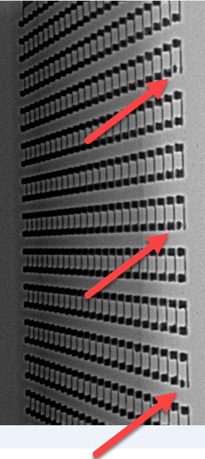
A sample with an open circuit in a pre-defined daisy chain was selected (the other daisy chains have good electrical continuity). In order to proceed with the magnetic inspection the heatsink was removed, exposing the substrate pads and the device was biased and inspected with a magnetic microprobe. (Each device has had 8 daisy chain tracks, track 1 at the top of the test part, and 8 at the bottom. The bump array has 24X24 bumps, so each daisy chain corresponds with three bumps lines).
The technique is promising but, it seems very dependant on the kind of available materials in the sample, and the distance, being in our case difficult to obtain useful information.
*The activity could be performed thanks to Fulvio Infante / Nicolas Courjault INTRASPEC TECHNOLOGY
Check the full paper with all the Optocap Assembly design and manufacturing, the test vehicle and test sample assignment, DPA flow for Flip`-chip construction, some DPA pictures, and the Summary and some of the conclusions after these studies.
Focusing on all aspects related to the usage of Commercial of the Shelf (COTS) Electrical, Electronic and electro-mechanical (EEE) parts in space applications. Although the main goal is to address the specific needs of “New Space” programs such as constellations and /or nano & small satellites, the workshop will cover also classical space missions.
Authors: Gonzalo Fernández (Technical Advisor) Alter Technology Tüv Nord
Ana Collado (Hybrid and Packaging Components Engineer) ESA_ESTEC
.
- Advances in Packaging and EEE Components - 19th March 2019
- Space Symposium Euroavia - 18th October 2018
- Test strategy for New Technologies and Nowadays Spacecraft Needs - 1st February 2016


