Scanning Acoustic Microscopy (C-SAM) for the non-destructive internal inspection of Microelectronic Parts: How it Works and Physics Fundamentals.
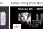
Scanning acoustic microscopy (SAM), also denominated acoustic micro imaging (AMI) and scanning acoustic tomography (SAT), is a consolidated and recognized tool for non-destructive quality control, inspection and failure analysis in microelectronics components and materials, which is routinely used for the inspection of plastic encapsulated integrated circuits amongst other systems (see Figure 1).

- Space
- Defense and Aerospace
- Automotive
- Power and Energy
- Materials analysis: ceramics and composites
Non-destructive inspection of microelectronic parts:
- Plastic encapsulated IC
- Flip Chip systems (CGA, FCBGA, PBGA, FPBGA…)
- Bonded Wafers
- Printed Circuit Boards
- Capacitors
- MEMS…
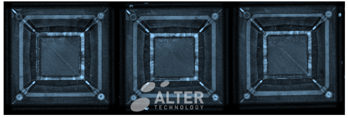
Figure 1. C-SAM internal inspection of three FPGAs
This complex characterization technique analyses the echoes generated at material interfaces to image hidden internal features. Thus, depth technological and scientific knowledge of the physical principles behind this powerful inspection technique is the base for the proper interpretation and understanding of the information obtained and the detected features. This post states the bases for the suitable understanding of SAM generated information.
Physics fundamentals
As illustrated in the figure, the working principle of the technique is based on the reflection that acoustic waves experience at media interfaces and density irregularities. The technique makes use of the high penetration depth of acoustic waves, in comparison to light, to image the internal structure of the specimen. Thus, in scanning acoustic microscopy either reflected or transmitted acoustic waves are processed to analyze the internal features.
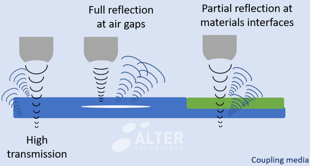
Figure 2. Physic principle
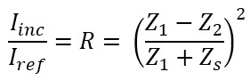
When the acoustic wave propagates thought the sample it may be scattered, absorbed or reflected at media interfaces. Thus, the technique registers the echo generated by the acoustic impedance (Z) contrast between two materials. The acoustic impedance is the acoustic counterpart of or the refractive index in optical microscopy and it is defined as:
Z = ρ x c
where ρ is de media density and c is the sound velocity in the propagation media. Therefore, similarly to light interaction, the ratio between the intensity of the incident and reflected beam at a material interface (reflection coefficient R) depends on the acoustic impedance of the involved media.
How it works and instrumentation
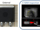
Acoustic microscopy techniques analyze the intensity and phase of both the reflected and transmitted waves to create visual images reflecting the variations in the acoustic impedance of the specimen, thereby disclosing internal flaws and defects such as delamination and voids. During this non-destructive test an ultrasound acoustic wave is generated by a piezoelectric transducer that converts electrical signals into acoustic signals and vice versa (detection stage). The acoustic waves are focalized, by means of a set of acoustic lenses, inside the specimen for the internal inspection of the system.
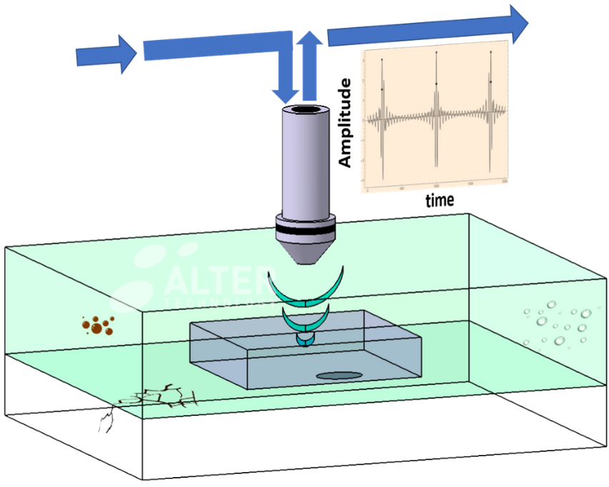
Figure 3. Working concept
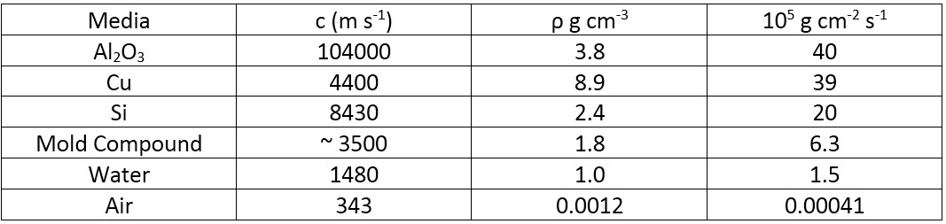
Table 1 lists the acoustic parameters of some materials commonly present in EEE parts. Note that at the interface between the mold compound and Si the reflection coefficient is positive and ~ 52 %. In contrast, in the case of a delamination or package cracks, i.e. at the interface between mold compound and air 100 % of the intensity is ideally reflected (no transmission), and the phase of the reflected pulse is inverted in relation to the incident pulse (R < 0). Therefore, both amplitude and phase analysis of the reflected signal can be used to identify internal delamination. In order to enhance the insertion of the acoustic wave into the specimen both the acoustic transducer and the sample are immersed in a coupling media, typically water, to avoid the high reflection at air interfaces.
Table 1. Acoustic parameters of martials typically present in EEE packing.
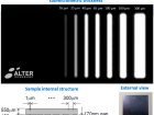
In addition to materials characteristics another important parameter to consider for a proper acoustic inspection is the probe frequency, as it determines the image resolution. In addition, the maximum penetration depth is also controlled by the frequency as illustrated in the following image. Therefore, inspection frequency must be properly selected as a function of the materials characteristics, the specimen thickness, depth of the target features and the required resolution.
Reflection Scan modes
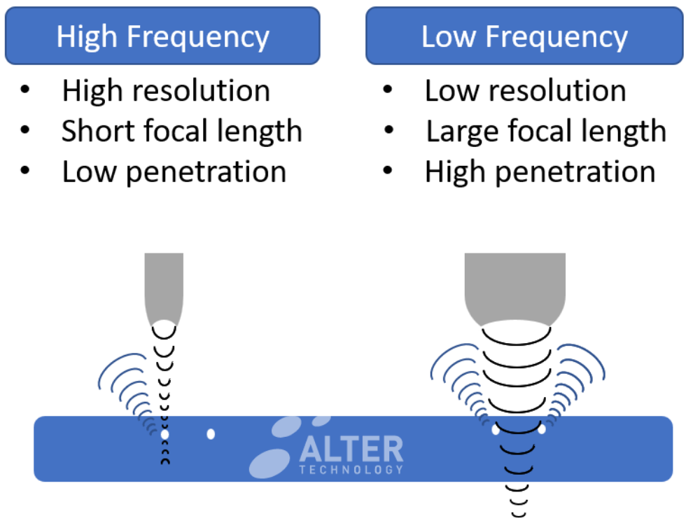
Figure 4. Frequency selection
A brief summary of different acoustic microscopy scan modes is included in another post. Depending on the scanning mode the technique analyses either the intensity of the transmitted beam or the amplitude and phase of the wave reflected at each interface.
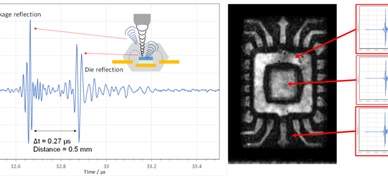
In the case of reflection scan-mode the image is generated from the detailed analysis of the time that the ultrasonic pulse takes to reach a given material interface and travel back to the transducer. This information is used to estimate specimen properties such as thickness, stiffness, density, shape, roughness and attenuation. A-Scan plots the reflected acoustic pulse at a given location. Thus, in the graph in Figure 5 the vertical scale corresponds to the amplitude (intensity) of the echo from different layers of the specimen; whereas the horizontal axis provides the wave travel time. In this example time delay is used to calculate the thickness of the different internal layers as well as the depth of internal features
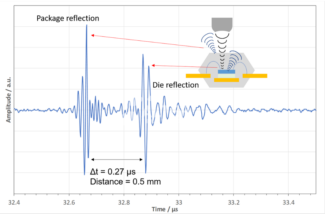
Figure 5. A-Scan dimension verification.
In C-SAM image the intensity of the echoes registered within the same time-window but at different location are used to reconstruct the surface features at a fixed depth. Hence, in a C scan a time window is created to exclusively accept those echoes from the depth of interest. This process is known as “gating” the returned echoes. In the generated images the bright areas are due to strong reflections such as those produced at air interfaces. As it was explained before, such high material-contrast may also modify the polarity of the reflected wave so phase analysis is an effective way for the accurate detection of air delamination.
Our commitment to quality
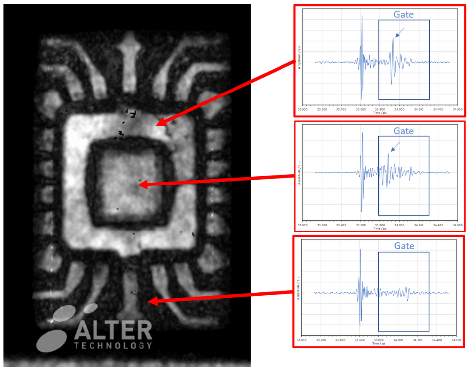
Figure 6. C-Scan reconstruction
In Alter Technology the Scanning Acoustic Microscopy Lab involves a qualified (Ph.D., M.Sc.) and multidisciplinary team specialized in different disciplines such as Materials Science, Physics, Electronics, and Aerospace Engineering; together with a highly experienced technical staff with a solid background in microscopy, materials analysis and EEE inspection. This team is supported by more than 30 years of experience of Alter technology in EEE testing and engineering.
- IPC/JEDEC J-STD-020E “Moisture Reflow Sensitivity Classification for Nonhermetic Surface Mount Devices”
- GEIA-STD-0006 “Requirements for Using Solder Dip to Replace the Finish on Electronic Piece Parts”
- MIL-STD-883 Test Method 2030“Ultrasonic Inspection of die attach”
- MIL-STD-1580 “Destructive Physical Analysis for Electronic Electromagnetic and Electromechanical Parts”
- MIL-PRF-123 ”Capacitors Fixed Ceramic Dielectric (Temperature Stable and General Purpose), High Reliability, General Specification For”
- MIL-PRF-31033 “Capacitor Fixed Ceramic Dielectric High Reliability Discoidal General Specification For”
- MIL-PRF-49470Capacitors, Fixed Ceramic Dielectric Switch Mode Power Supply (General Purpose and Temperature Stable) Standard Reliability and High Reliability, General Specification For

Contact us

Since 2007 Dr Aparicio has developed a productive research career within the field of Materials Science including post-doctoral stays at the University of Trento, the University of Mons, and the Spanish National Research Council (CSIC). His researches have been published in more than 30 articles in reputed international research journals and conferences (> 70) including more than 10 invited talks and lectures.
Within the frame of the programme “Torres Quevedo” for the Knowledge Transfer and the incorporation of research talent into the industry, in 2019 he joined Alter Technology as Senior Materials Science Test Engineer. In 2019 he was appointed to lead the Scanning Acoustic Microscopy Service. Within this framework, he currently collaborates in different ESA projects (JUICE and PLATO).”
- Scanning Acoustic Microscopy on Ceramic Capacitors - 18th May 2020
- Non-destructive detection of micrometric internal features within EEE microelectronic systems. - 3rd September 2019
- Acoustic Inspection of Hybrid Systems on Laminated Substrates - 3rd September 2019